Bachelor's thesis at Parul University, October 2022 to March 2023.
The Hand
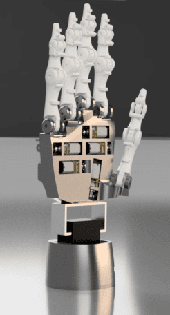
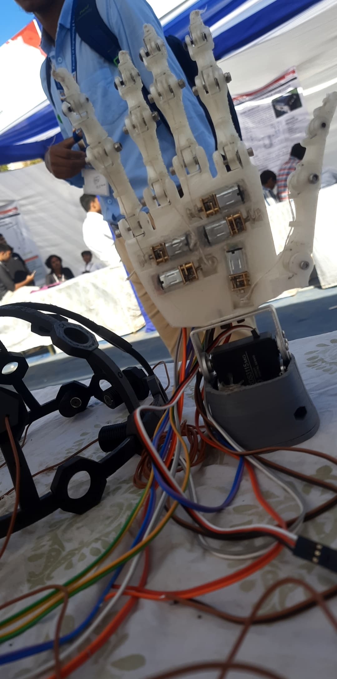
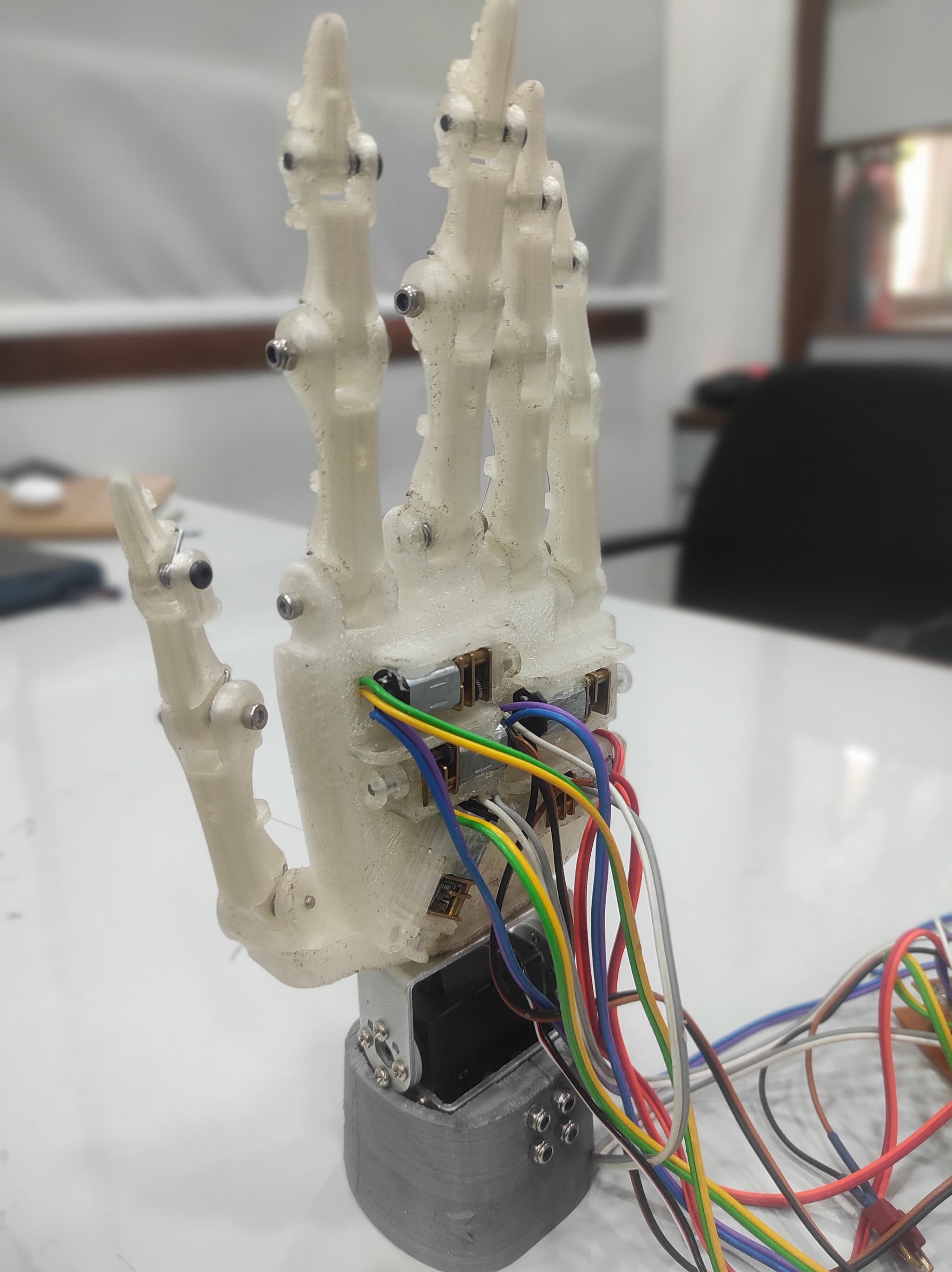
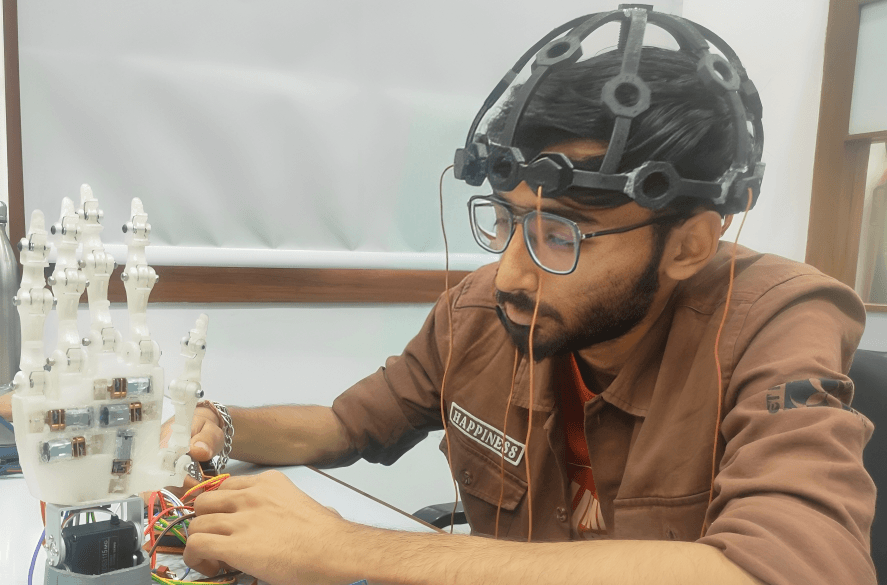
The prosthetic covers the hand and palm only. It has five fingers, each with three degrees of freedom, actuated by a tendon-driven mechanism with one gear motor per finger. A wrist joint adds one additional axis controlled by a servo. The entire structure was designed in Fusion 360 and 3D printed in PLA+.
The tendon drive keeps the motors in the palm rather than distributing them through the fingers. Each motor pulls or releases a tendon routed through the finger joints to produce flexion and extension. This reduces mass in the distal segments and allows the finger geometry to stay closer to anatomical proportions.
BCI System
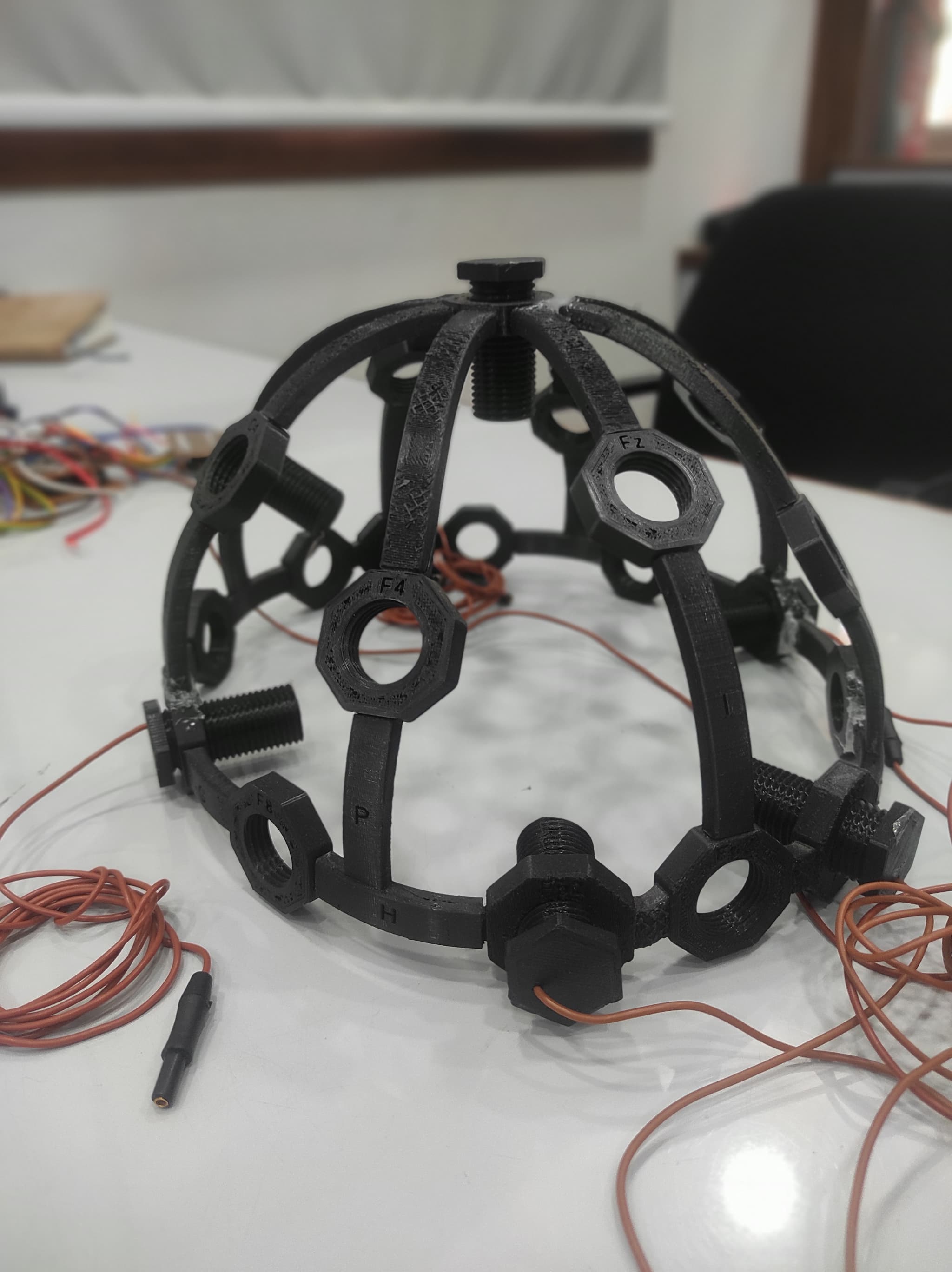
The EEG hardware was fully custom. A 3D-printed headset frame holds gold-plated electrodes at four active positions on the scalp: Fp1, Fp4, F3, and F4. A ground electrode sits behind the ear. These positions target the frontal and prefrontal regions adjacent to the motor cortex, which produces alpha waves in the 8 to 12 Hz range and beta waves in the 13 to 30 Hz range during motor activity and motor imagery.
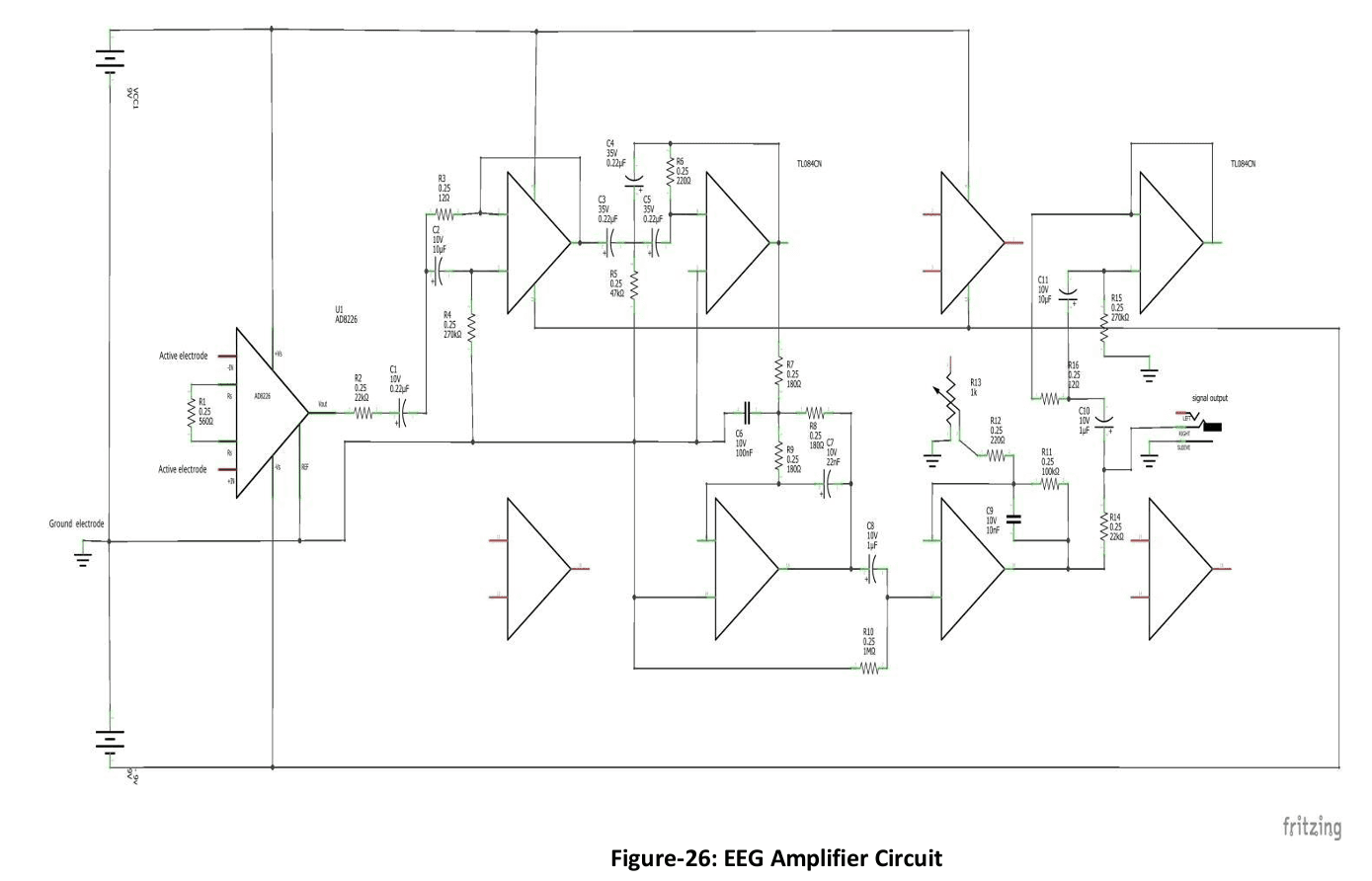
The amplification circuit was designed and built from scratch using AD622 and AD623 instrumental amplifiers across six stages. The first stage is a differential instrumental amplifier for initial signal acquisition. The second stage is a 60 Hz notch filter to reject mains interference. The third is a 7 Hz high-pass filter to remove baseline drift. The fourth is a 31 Hz low-pass filter to isolate the alpha and beta frequency bands. The fifth is a variable gain stage for scaling. The sixth is a second 60 Hz notch filter to catch any residual mains noise that passed through the first. EEG signals are in the microvolt range, which makes the ordering and isolation of these stages critical.
Electronics
Signal acquisition and processing run on STM32 and Arduino microcontrollers. An Arduino Nano sits on the prosthetic side and handles motor commands. A Waveshare ESP32 serial bus servo driver handles servo communication for the wrist. The gear motors are driven by an L293D H-bridge driver. Separate voltage regulators supply 6V to the servos, 5V to the microcontrollers, and 3.3V to the gear motors.
Control Logic
At the time of submission, classification was threshold-based. The processed EEG signal is read across two channels corresponding to different electrode pairs. An alpha or beta power spike on channel A commands the fingers to close. A spike on channel B commands the fingers to open. Simultaneous spikes on both channels command a wrist movement. A steady 7 to 8 Hz baseline on both channels means no motion.
After the thesis was submitted, I ran experiments using k-nearest neighbors and support vector machine classifiers as alternatives to the threshold approach, running them on the STM32 and Arduino. These were not deployed results, but classification accuracy under clean signal conditions was noticeably better than the threshold method.
Challenges
The two main problems were noise isolation in the custom amplifier circuit and electrode contact reliability.
EEG signals are on the order of microvolts. The 60 Hz mains interference present in any lab environment is large relative to that, and movement artifacts from the facial muscles near the frontal electrode positions add additional contamination. The multi-stage filtering approach brought the signal to a usable state, but the custom circuit could not reach the noise floor of commercial EEG hardware. The threshold-based classifier had to be tuned conservatively to avoid false triggers from residual noise, which limited how responsive the prosthetic could feel.
Maintaining consistent electrode contact was the other persistent issue. The gold-plated electrodes made reliable electrical contact through hair when sufficient pressure was applied, but that pressure became uncomfortable during longer sessions. When contact quality dropped, signal amplitude fell and either produced false commands or no response at all. Resolving this properly would require a different electrode design, a wet electrode approach, or a higher contact-area geometry.
Outcome
The system successfully demonstrated brain-controlled finger and wrist movement. The user could open and close the fist and rotate the wrist to a desired angle by imagining the corresponding motion. This was the first system I built that closed the loop from a biological signal to a physical mechanical output, and it established the foundation for understanding how difficult reliable biological signal acquisition actually is at this scale.